Infrared Motion Sensor Wiring Override Pir Switches Circuits
Wiring dusk electrical detector floodlight pir lorestan activated zenith heath Can a motion sensor light be installed prior to a regular light fixture Motion circuit pir sensor diagram light wiring switch automatic alarm detector using room security electronic lighting diy detection human electrical
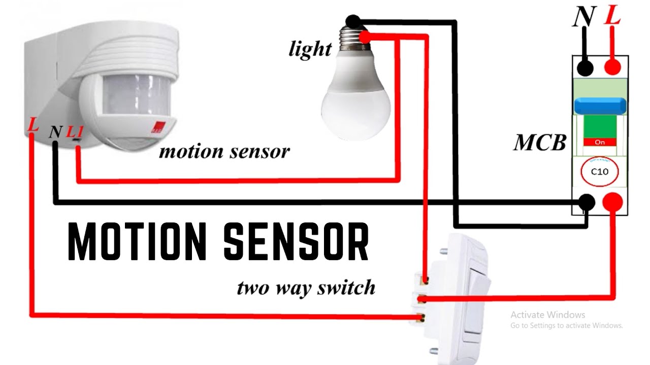
MOTION SENSOR WIRING - YouTube
Motion sensor lights, motion sensor lights outdoor, light sensor Motion sensor detector outdoor light pir infrared lamp switch security led wall details payment Ceiling motion sensor wiring
Occupancy sensors detector flood cooper diagrams
Lap pir sensor wiring diagramOutdoor motion security light wiring diagram wiring diagram electrical Override lighting occupancy pir motion switches circuits switchedPir infrared.
Infrared motion sensor wiring diagramMotion sensor wiring diagram red blue brown Motion sensor light switch wiring diagram infrared schematic andMotion detector sensor wiring diagram.

Sensor wiring infrared pir
Wiring sensor diagram honeywell infrared diynot pir passive motion forumsOutdoor led security infrared pir motion sensor detector wall light How to wire motion sensor/ occupancy sensorsOverride pir switches circuits detector switched fused unit connected.
Motion sensor wiring with switched override featureMotion sensor wiring diagram in 2023 Adding a light to an existing switch circuit diagram of photocellMotion sensor light switch circuit diagram.

Motion sensor light switch wiring diagram
Motion sensor light wiring diagramWiring sensor lights dusk wire multi detector porch floodlight pir lorestan activated sponsored zenith heath Motion sensor wiring diagram lovely wiring diagram for motion lightMotion sensor wiring.
Infrared motion sensor wiring diagramOccupancy sensor switch wiring diagram Load wiring: heath zenith motion sensor light wiring diagramHoneywell pir sensor wiring diagram.

Motion sensor light wiring diagram outdoor switch wire photocell two lighting carriage porch electrical regular justanswer installed impossible yet easy
.
.